


The Essential Components and Functions of Composite Video Signals
This detailed guide is designed to boost your knowledge of CCTV functionalities, specifically focusing on the composite video signal. Originating at the camera, this fundamental electrical signal travels to the control room via a transmission system, playing a vital role in CCTV operations. In this article, we will examine the components of this composite video signal and understand each element’s purpose.
Constituents of a Composite Video Signal
The composite video signal comprises several elements, including:
- Video Signal
- Horizontal Sync Pulse
- Vertical Sync Pulse
Let’s examine each of these in more detail.
The Video Signal
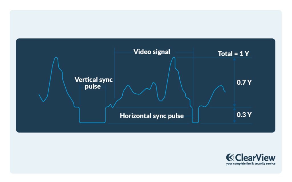
When light falls on a Charge-Coupled Device (CCD) chip, it instigates a charge within the pixels proportional to the light intensity. A greater amount of light corresponds to a larger charge. This charge is then converted into a video signal. The process of reading this charge varies depending on the type of CCD chip. In a composite video, the video signal has a maximum amplitude of 0.7 volts. This means the bright parts of the picture, the white elements, will have a signal strength of 0.7 volts, while the darker, black parts will register a signal of 0 volts.
Vertical Sync Pulses
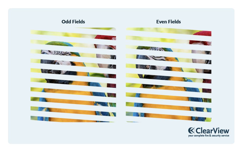
A video picture comprises multiple video frames. NTSC, for instance, utilises 30 frames per second (fps), while PAL uses 25 fps. To prevent flickering, this video frame is subdivided into two fields, termed the ‘odd’ and ‘even’ fields. These fields are separated at the camera and later recombined at the monitor, a process known as ‘interlacing’ of fields.
Each frame or field concludes with a vertical sync pulse. This pulse indicates to the electronic devices within the camera and other CCTV components that the current field has ended and the next one is about to start. The pulse’s duration is dictated by the time electronic devices take to receive the next field, with an amplitude of 0.3 volts.
Horizontal Sync Pulse
A video frame consists of lines, with NTSC containing 525 lines per frame and PAL encompassing 625 lines. Each point along the line mirrors the intensity of the video signal. The conclusion of each line is marked by a horizontal sync pulse, informing the CCTV system’s electronic devices that a line has ended and the next is about to commence. This pulse also carries an amplitude of 0.3 volts.

Frequencies of Horizontal and Vertical Scanning
Let’s delve into the different frequencies within the PAL and NTSC systems:
| NTSC | PAL | |
|---|---|---|
| Frame Frequency | 30/sec | 25/sec |
| Duration of each frame | 1/30 sec | 1/25 sec |
| No of fields per frame | 2 | 2 |
| Field frequency | 60/sec | 50/sec |
| Duration of each field | 1/60 sec | 1/50 sec |
| No of lines per frame | 525 | 625 |
| No of lines per field | 262.5 | 312.5 |
| No of lines per sec | 15750 | 15625 |
| Duration of each line | 63.5 us | 64 us |
Horizontal and Vertical Blanking
‘Blanking’ refers to the period when no picture information is being scanned and is denoted by the screen ‘going to black level’. This period must be rapid, as it’s essentially wasted time with no picture information conveyed. Approximately 16% of each horizontal line and about 8% of the vertical field is dedicated to this retrace time.
Here are the specific measurements for NTSC and PAL systems:
| NTSC | PAL | |
|---|---|---|
| Field duration | 1/60 sec | 1/50 sec |
| Vertical blanking | 1333 us | 1600 us |
| Line loss due to vertical blanking | 21 lines | 25 lines |
| Line duration | 63.5 us | 64 us |
| Horizontal blanking | 10.2 us | 10.25 us |
| Visible trace time | 53.3 us | 53.75 us |
Horizontal and Vertical Synchronisation
The synchronisation pulse initiates the actual retrace in scanning. The horizontal sync pulse is inserted in the video signal during the horizontal blanking pulse, while the vertical sync pulse is inserted during the vertical blanking time. The frequencies for each synchronisation pulse in NTSC and PAL are as follows:
| NTSC | PAL | |
|---|---|---|
| Vertical | 60 Hz | 50 Hz |
| Horizontal | 15750 Hz | 15625 Hz |
Colour Signals in CCTV
A colour video signal is akin to a monochrome signal, but with additional colour information, transmitted separately. This includes:
- Luminance signal (Y signal): Contains the variations in the picture information as seen in a monochrome signal, reproducing the picture in black and white.
- Chrominance signal (C signal): Contains the colour information, transmitted as the modulation on a sub-carrier. The sub-carrier frequency is 3.58 MHz for NTSC and 4.43 MHz for PAL.
In a colour receiver, the chrominance signal is combined with the luminance signal to produce a colour picture. However, in a monochrome receiver, the chrominance signal isn’t used, and the picture is reproduced in black and white.
Constructing the Composite Video Signal
The composite video comprises:
- Camera signal output corresponding to the scene’s light variations
- Synchronisation pulses for scanning
- Blanking pulses to make the retrace invisible
- For colour signals, the chrominance signal and colour sync burst are included.
Conclusion
Grasping the workings of composite video signals is critical in understanding the broader functionalities of CCTV systems. As we’ve learned, these signals are composed of various elements, all intricately working together to ensure seamless transmission from the camera to the control room. From the video signal itself to vertical and horizontal sync pulses, each component plays a pivotal role.
While the technical aspects might seem daunting at first, breaking down each part can significantly demystify the process. Whether you’re just embarking on your journey in CCTV operation or looking to refresh your existing knowledge, we hope this guide has proven informative and helpful.
References
- Understanding the Video Signal – PDF
- Understanding Lenses – PDF
- Understanding Camera Specifications – PDF
Read next – Understanding Camera Specifications

